Exercise: Msi Logic Circuits

Questions for: Msi Logic Circuits

The IEEE/ANSI symbol for a decoder has the internal designation bcd/dec. This means the decoder is a:
A:
decimal-to-BCD decoder with ten inputs and four outputs.
B:
BCD-to-decimal decoder with ten inputs and four outputs.
C:
decimal-to-BCD decoder with four inputs and ten outputs.
D:
BCD-to-decimal decoder with four inputs and ten outputs.
Answer: D
No answer description is available. Let's discuss.

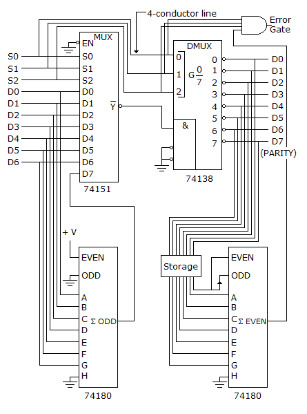
The data transmission system shown in below has a problem; the parity error output is always high. A logic analyzer is used to examine the system and shows that the DATA IN on the left matches the DATA OUT on right. What might be causing the problem?

A:
The error gate could be defective.
B:
The storage circuit could be defective.
C:
The parity checker could be bad.
D:
Any of the above.
Answer: D
No answer description is available. Let's discuss.

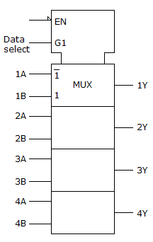
Which statement best describes the given figure, and what is the function of the terminal labeled EN?

A:
Quad two-input multiplexer. EN is the enable input, which requires an active LOW for the device to work.
B:
Quad two-bit multiplier, EN is the active HIGH trigger.
C:
Dual quad-input multiplexer, which requires an active LOW on the EN terminal for the device to work.
D:
Quad two-input AND gate, which requires an active LOW on the EN input to enable all the gates.
Answer: A
No answer description is available. Let's discuss.

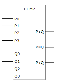
It is suspected that the comparator in the figure given below has a problem. The inputs are activated in the table shown below and the corresponding outputs noted. What is most likely wrong with the circuit?
For P0 – P3 = 1 and Q0 – Q3 = 0, P > Q = 1, P = Q = 1, P < Q = 0
For P0 – P3 = 0 and Q0 – Q3 = 1, P > Q = 0, P = Q = 1, P < Q = 1
For P0 – P3 = 1 and Q0 – Q3 = 1, P > Q = 0, P = Q = 1, P < Q = 0

A:
The P0–P3 inputs are defective.
B:
One or more of the Q inputs is bad.
C:
The P = Q output is shorted to Vcc.
D:
Nothing is wrong; the circuit is functioning properly.
Answer: C
No answer description is available. Let's discuss.

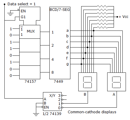
For the input values (A0–A3, B0–B3, Data Select = 1) given for the circuit given below, what will be indicated on the displays?

A:
A = 0, B = 5
B:
A = 5, B = 0
C:
A = 6, B = 0
D:
A = 0, B = 6
Answer: D
No answer description is available. Let's discuss.
Ad Slot (Above Pagination)
Quiz