Exercise: Exam Question Papers
Questions for: Exam Question Papers
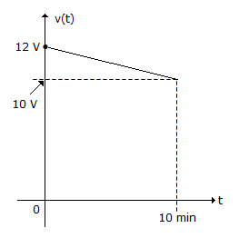
A fully charged mobile phone with a 12 V battery is good for a 20 minute talktime. Assume that, during the talk time, the battery delivers a constant current of 2 A and its voltage drops linearly from 12 V to 10 V as shown in the figure. How much energy does the battery deliver during this talk time?
Answer: C
No answer description is available. Let's discuss.
The input impedance of figure given below is

A:
Rg(1 + Av)
B: 
C:
Rg(1 - Av)
D: 
Answer: C
No answer description is available. Let's discuss.
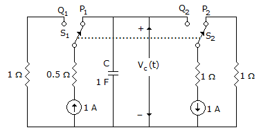
The circuit shown in the figure is used to charge the capacitor C alternately from two current sources as indicated. The switches S1 and S2 are mechanically coupled and connected as follow
For 2nT ≤ t < (2n + 1)T, (n = 0, 1, 2, ...) S1 to P1 and S2 to P2
For (2n + 1) T ≤ t < (2n + 2)T, (n = 0, 1, 2, ...) S1 to Q1 and S2 to Q2
Assume that the capacitor has zero initial charge. Given that u(t) is a unit step function, the voltage Vc(t) across the capacitor is given be
For 2nT ≤ t < (2n + 1)T, (n = 0, 1, 2, ...) S1 to P1 and S2 to P2
For (2n + 1) T ≤ t < (2n + 2)T, (n = 0, 1, 2, ...) S1 to Q1 and S2 to Q2
Assume that the capacitor has zero initial charge. Given that u(t) is a unit step function, the voltage Vc(t) across the capacitor is given be
A:  (- 1)n tu(t - nT)
(- 1)n tu(t - nT)B:
u(t) + 2 (-1)n u(t - nT)
(-1)n u(t - nT)C:
tu(t) + 2 (-1)n (t - nT) u(t - nT)
(-1)n (t - nT) u(t - nT)D: [0.5 - e-(t - 2nT) + 0.5e-(t - 2nT - T) ]
[0.5 - e-(t - 2nT) + 0.5e-(t - 2nT - T) ]
Answer: A
No answer description is available. Let's discuss.
Ad Slot (Above Pagination)
Discuss About this Question.